 All-in-One COB LED TV
  Flexible LED Displays
  Transparent LED Displays
  Led Poster
  Circular LED Displays
  Creative & Custom LED Displays
 COB Beta P1.5 Sand Table Display in Shanghai
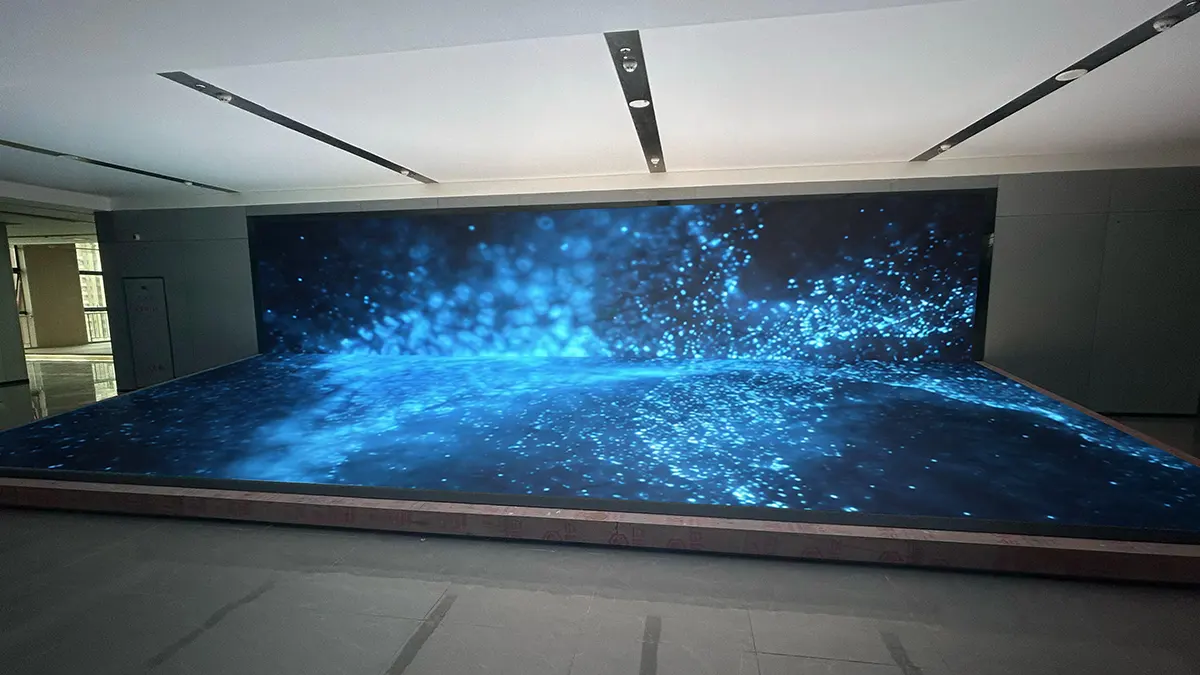
A corporate showroom operator in Shanghai needed an L-shaped immersive digital sand table — 9.6 meters wide, combining a 30.72 m² floor display with a 23.04 m² LED wall. The challenge: P1.5 SMD modules at this scale are notoriously fragile. Every assembly cycle risks dead pixels from finger pressure, tool contact, or crowd proximity. The solution? COB Beta's epoxy encapsulation — turning 1,050 modules into 1,050 impact-resistant boards that survive frequent teardown and rebuild without a single casualty. Driven by 3 × NovaStar MCTRL4K processors synchronized across 37 Ethernet ports.
At a Glance
A 54 m² Sand Table Where Fine Pitch Meets Crowds
The question wasn't whether P1.5 could deliver the visual quality. It was whether P1.5 could survive the installation — and the re-installation after that.
A corporate showroom operator in Shanghai wanted an L-shaped digital sand table — 9.6 meters wide, consisting of a 30.72 m² floor display and a 23.04 m² LED wall rising behind it. The brief was straightforward: an immersive digital canvas where the floor layer renders GIS maps, floor plans, and 3D terrain models, while the vertical wall plays brand narratives synchronized with the sand table content.
But here's the rub: P1.5 at 54 m² means roughly 24 million pixels spread across 1,050 individual LED modules. Each module is a palm-sized board covered in tiny LED chips spaced 1.5 millimeters apart. At this density, a single LED die is barely visible to the naked eye — and just as fragile. SMD modules at P1.5 are notorious for losing pixels during assembly. A technician's fingertip pressing on the wrong spot, a screwdriver slipping, or modules stacked face-to-face during transport — any of these can shear off multiple LED chips in an instant.
And this client's showroom operates on a rotating exhibition schedule. The sand table would be assembled, disassembled, and reassembled multiple times. Each cycle with SMD would be a dice roll on dead pixel count. Each dead pixel requires removing the module, desoldering the broken chip, soldering a replacement, and recalibrating — a process that, repeated across a thousand modules, turns maintenance into a full-time job.

COB vs SMD: The Fragility Equation
SMD modules at P1.5 are precision optical instruments. The problem is they're treated like building blocks.
To understand why we specified COB Beta for this project, you need to understand what happens to an SMD P1.5 module during a single assembly cycle:
- Finger PressureTechnicians handle modules by their edges during installation, but accidental contact with the LED surface is inevitable at scale. An SMD lamp bead at P1.5 measures roughly 0.5mm across — pressing a thumb onto the surface can crush multiple chips simultaneously.
- Tool ContactDuring magnetic mounting or alignment, a screwdriver, pry tool, or even a fingernail can nick exposed SMD lamp beads. At P1.5 density, one slip can disable a cluster of 4–6 pixels.
- Transport StackingModules are transported face-to-face with foam separators. SMD lamp beads protrude from the PCB surface; any pressure concentration during stacking — a grain of debris, an uneven foam sheet — creates a point load on the exposed chips.
- Crowd ProximityEven after installation, the sand table sits in a high-traffic exhibition zone. Visitors lean over the display, point at details, and occasionally brush against the surface with watches, rings, or bags — all of which can damage exposed SMD chips.
COB (Chip-on-Board) encapsulates every LED chip under a continuous layer of epoxy resin. The surface is a single, seamless, 5H-hardness shield — not thousands of individual exposed lamp beads. When a technician presses the surface, the force distributes across the epoxy plane. When a visitor's watch brushes against it, there's nothing to shear off. The module is effectively a solid-state optical panel, not a fragile PCB covered in bare micro-components. And critically, COB Beta delivers this durability at P1.5 — a pitch where SMD fragility becomes the dominant maintenance cost driver.
3 × MCTRL4K Driving 24 Million Pixels
53.76 m² at P1.5mm pitch generates approximately 24 million pixels — the equivalent bandwidth of three simultaneous 4K streams running at 60Hz. A single standard LED sending card handles at most 8.84 million pixels (one MCTRL4K), so the math dictated a minimum of three units.
But raw pixel count isn't the only bottleneck. Each gigabit Ethernet output from a sending card maxes out at roughly 650,000 pixels under standard 8-bit/60Hz conditions. For 24 million pixels:
We deployed three NovaStar MCTRL4K processors with a sync card to maintain frame-level synchronization across all three units. The topology splits logically: two MCTRL4K units drive the floor sand table (30.72 m² ≈ 13.7M pixels), and the third handles the vertical LED wall (23.04 m² ≈ 10.2M pixels). The sync card ensures both surfaces display the same frame simultaneously — so when a camera pans across a 3D city model on the sand table, the brand video on the wall transitions in lockstep.
The NovaStar VX1000 supports up to 13 million pixels — theoretically two units could handle 24M. But at 12M per unit, both processors would run near their ceiling with zero headroom. Three MCTRL4K units at 8M each provide comfortable margin for future module additions, reduce single-point-of-failure risk, and cost approximately the same as two VX1000s. For a client who plans to reconfigure and expand the sand table over time, headroom is not a luxury — it's a requirement.
On the receiving side, MRV336 receiver cards (256×256 pixel capacity each) were distributed across the 1,050 COB Beta modules. Each receiver card drives two modules, with 37 active Ethernet ports each feeding 14–15 receiver cards — well within the recommended load per port. This conservative distribution means no single port is at risk of frame drops even under peak content load.


Project Specs
From Shenzhen to Shanghai in Three Weeks
Base Iron Layer Integration
Client's sand table base contractor embedded a thin iron absorption layer into the top surface during fabrication. DOIT VISION provided the magnetic mounting specifications and iron layer thickness requirements.
Production & Aging
1,050 COB Beta P1.5 modules manufactured in Shenzhen. Full burn-in aging test — each module passed zero dead pixel inspection before packaging into foam-lined transport cases.
Magnetic Installation
Modules placed directly onto the iron layer — no tools, no welding, no custom frames. 600 floor modules laid in under one day. 450 wall modules mounted to aluminum backing plate with magnetic strips.
MCTRL4K Sync & Calibration
Three MCTRL4K units configured with sync card for frame-level lock. 37 Ethernet ports mapped to 525 MRV336 receiver cards. Color calibration applied across the L-shaped canvas for seamless floor-to-wall transition.

A real photo from the installation floor below — the display captured with a portion of modules lit during commissioning. The full synchronized effect is shown in the design render at the top of this page.
Worried about dead pixels after assembly?
COB epoxy eliminates the SMD fragility problem. Get a free LED protection comparison from our engineering team — COB vs SMD failure rates, real field data, and a rough cost comparison within 48 hours. No sales pitch, just numbers.
Frequently Asked Questions
Why choose COB instead of SMD for fine-pitch displays that get frequently assembled and disassembled?
Is P1.5 resolution enough — or should I pay more for P0.9?
COB Beta vs COB Pro — which COB product line should I choose?
How many NovaStar processors do I need for a 54m² P1.5 LED wall?
Can LED modules be mounted directly onto an existing base without building custom cabinets?
Does magnetic mounting hold reliably for large installations like this?
What is the typical lead time for a COB sand table project of this scale?
Products & Resources
COB Beta Series
P1.2–P2.5 COB LED for indoor fixed installations. 5H epoxy encapsulation, impact-resistant, magnetic mounting. The workhorse for durable fine-pitch.
Explore →COB Pro Series
P0.62–P1.875 flagship COB. Flip-chip, 10,000:1 contrast. For command centers, broadcast, and sub-1mm viewing.
Explore →Fine Pitch LED Displays
Compare COB Pro, COB Beta, MIP & All-in-One series. Pixel pitch calculator and viewing distance guide included.
Explore →LED Display Calculator
Input your room dimensions and viewing distance. Get optimal pixel pitch, resolution, and processor count recommendations.
Explore →Your Custom Shape, Engineered
Send drawings or a rough diameter/height sketch — we will assess whether a flexible solution alone works. Reply within 48 hours.
WhatsApp an Engineer Get a Quote View All Case Studies