 All-in-One COB LED TV
 Flexible LED Displays
 Transparent LED Displays
 Led Poster
 Circular LED Displays
 Column LED Screens
 Creative & Custom LED Displays

Control rooms
Size the native pixel grid around the smallest text and simultaneous source windows. Check the closest operator position, signal layout and working space for front service.
Plan a Control-Room WallFine-Pitch LED Display
Indoor COB LED video walls for close-view presentations, dashboards and display installations. Match the pixel pitch to your wall opening, native resolution and viewing distance.
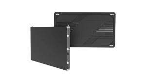
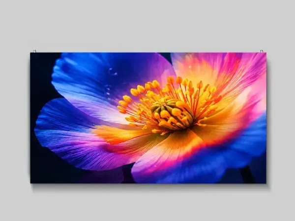
COB Pro uses a die-cast aluminium cabinet with a 16:9 pixel grid. Six pitches share the same cabinet footprint, so the required native resolution and available wall size can determine the configuration.
Front service supports installations against a wall or on a project-specific frame. A 3-in-1 hub-board architecture brings the cabinet connections together; the processor and signal inputs are specified with the project.
| Pitch / SKU | Cabinet pixels | Brightness (nits) | Refresh (Hz) |
|---|---|---|---|
| P0.62 · CP-I-P062 | 960×540 | 600 / 1000 | 3840 / 7680 |
| P0.78 · CP-I-P078 | 768×432 | 600 / 1000 | 3840 / 7680 |
| P0.9375 · CP-I-P093 | 640×360 | 600 / 1000 | 3840 / 7680 |
| P1.25 · CP-I-P125 | 480×270 | 600 / 1000 | 3840 |
| P1.5625 · CP-I-P156 | 384×216 | 600 / 1000 | 3840 |
| P1.875 · CP-I-P187 | 320×180 | 600 / 1000 | 3840 |
Use cabinet pixels to size the active display. Allow additional space for the frame, trim, cabling and installation access.
Size the native pixel grid around the smallest text and simultaneous source windows. Check the closest operator position, signal layout and working space for front service.
Plan a Control-Room Wall
Presentations, spreadsheets and video calls need clear text from the nearest and furthest seats. Match the wall dimensions and native resolution to the content, then review window light and source connections.
Plan a Meeting-Room Wall
Plan the display around visitor routes and close-view content. For corner or curved layouts, review the outline, cabinet connections and supporting structure with the site drawings.
Plan a Showroom DisplayThe cabinet is 33 mm deep. Add the back frame, power and signal routes, ventilation and working clearances when checking the wall recess.
Allow access at the display face. Match spare modules, power supplies and receiving equipment to the selected SKU and configuration.
Product drawings, back-frame drawings and CAD design support are available for indoor fixed installations. Custom frames are quoted to the project scope.
Corner and arc installations use project-specific cabinet and supporting-structure arrangements. Geometry and connections are reviewed against the required outline.

| Specification | CP-I-P062 | CP-I-P078 | CP-I-P093 | CP-I-P125 | CP-I-P156 | CP-I-P187 |
|---|---|---|---|---|---|---|
| Pitch (mm) | 0.62 | 0.78 | 0.9375 | 1.25 | 1.5625 | 1.875 |
| Pixel density (px/m²) | 2560000 | 1638400 | 1137777 | 640000 | 409600 | 284444 |
| Brightness (nits) | 600 / 1000 | 600 / 1000 | 600 / 1000 | 600 / 1000 | 600 / 1000 | 600 / 1000 |
| Refresh rate (Hz) | 3840 / 7680 | 3840 / 7680 | 3840 / 7680 | 3840 | 3840 | 3840 |
| Module pixels | 240×270 | 192×216 | 160×180 | 120×135 | 96×108 | 80×90 |
| Cabinet pixels | 960×540 | 768×432 | 640×360 | 480×270 | 384×216 | 320×180 |
| Average power (W/m²) | 135 | 135 | 120 | 115 | 115 | 105 |
| Maximum power (W/m²) | 420 | 420 | 370 | 345 | 345 | 320 |
| Control system | Novastar | Novastar | Novastar | Novastar | Novastar | Novastar / Colorlight |
Equipment and document illustrations are references; your quotation and packing list define the supplied items and quantities.
600 × 337.5 mm COB Pro cabinets in the selected pixel pitch. Cabinet quantity, layout and native resolution follow the order configuration.
A custom back frame can be specified for the wall dimensions and installation method. Mounting hardware and quantities are confirmed in the project quotation.
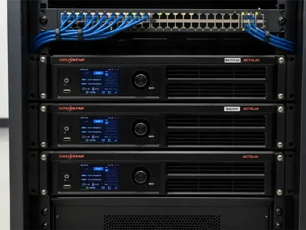
Control equipment is specified for the native pixel map and source requirements. Power and signal cables are itemised for the installation.
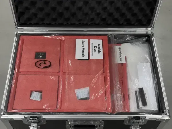
Spare modules are matched to the selected pitch and configuration. The agreed spare-parts list records the supplied items and quantities.
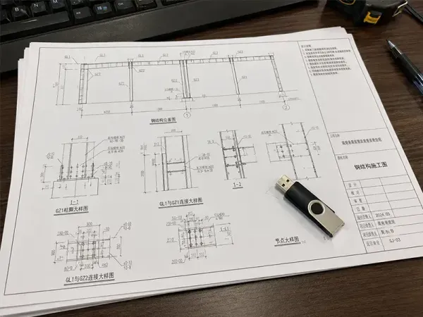
Product and back-frame drawings, wiring diagrams and installation instructions support the project. Drawings are coordinated with the site dimensions and mounting requirements.

Order-specific test videos, FAT inspection records, packing photographs and spare-parts lists are available for acceptance and handover.
Model specifications, cabinet pixels, power and control options.
Download DatasheetProduct structure, layout examples and project-planning information.
COB Pro is available in P0.62, P0.78, P0.9375, P1.25, P1.5625 and P1.875. All six use a 600 × 337.5 mm cabinet, while cabinet pixels and power change with the pitch. The P0.9 market class corresponds to our P0.9375 model. Specify the exact SKU and cabinet resolution when comparing quotations or preparing the display layout.
A native 3840 × 2160 COB Pro wall measures 3.0 × 1.6875 m at P0.78, 3.6 × 2.025 m at P0.9375, or 4.8 × 2.7 m at P1.25. These use 5 × 5, 6 × 6 and 8 × 8 cabinets respectively. Dimensions describe the active display; the mounting frame, trim and installation clearances require additional space.
P0.62, P0.78 and P0.9375 offer 3,840 Hz or 7,680 Hz configurations. P1.25, P1.5625 and P1.875 are specified at 3,840 Hz. Confirm the selected refresh rate, brightness and control configuration in the quotation. For camera-facing work, evaluate the display with the intended camera, shutter settings and content, because refresh rate alone does not determine the recorded result.
The COB Pro cabinet is 33 mm deep. Total installation depth also includes the mounting frame, power and signal routing, ventilation and access required by the installation. Send the available wall recess, supporting-wall details and site photographs for a layout review. Product and back-frame drawings can be supplied for indoor fixed-install projects, with the structure designed around the site conditions.
COB Pro is designed for front service, giving access from the display side for maintenance. The installation layout should provide working space for the technician and the specified service tools. Spare parts must match the selected pitch and configuration. Include the replacement-parts list, wiring documentation and service procedure in the project handover so the local team can plan maintenance.
The quotation and packing list define the cabinet quantity, control equipment, cables, mounting parts and agreed spare parts. Matching replacement parts and service tools are specified for the selected configuration. Product and mounting drawings, wiring diagrams and installation instructions support the project. Order-specific test videos, FAT records, packing photographs and spare-parts lists are available for acceptance and handover.
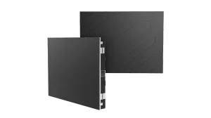
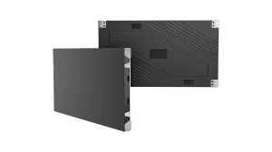
Share the wall opening, content and closest viewing distance. We can review the pitch, cabinet layout and itemised quotation scope.
A drawing, a site photo or an early idea. Tell us what you are planning and work through the details with our engineering team.