 All-in-One COB LED TV
  Flexible LED Displays
  Transparent LED Displays
  Led Poster
  Circular LED Displays
  Creative & Custom LED Displays
 Start Here
What can this LED calculator calculate?
Pick your starting point. It will directly jump to the correct calculator module.
Module 01
What Pixel Pitch
Do I Need?
Enter your minimum viewing distance and environment. The calculator returns the recommended pixel pitch and maps the result to DOIT VISION products.
Formulas used in this calculation
Enter parameters and click Calculate
Module 02
What Size Screen
Will I Get?
Enter cabinet dimensions, pixel pitch, and the number of cabinets wide and high. Returns exact screen dimensions, total resolution, and aspect ratio.
Select a product and cabinet count to calculate
Module 03
How Many
Cabinets Do I Need?
Enter your target screen size and cabinet dimensions. Returns the exact cabinet count, actual achievable dimensions, overshoot in mm, and total area.
Enter target size and cabinet format to calculate
Module 04
What Are the
Viewing Distances?
Enter pixel pitch and screen dimensions. Returns minimum, optimal, and maximum viewing distances — and the full usable viewing zone for your space.
Formulas used in this calculation
Enter pixel pitch and screen size to calculate
Module 05
Power Draw
and Weight.
For electrical engineers and structural engineers. Enter product and total screen area. Returns max and average power draw, total weight, circuit count, and recommended MCB rating.
Formulas used in this calculation
Select product and enter screen area to calculate
Engineering Reference
Calculation Methodology
&
Technical
Reference.
Industry-standard formulas and engineering principles behind each calculator module. Suitable for AV project proposals, tender documentation, and engineering design reports.
Pixel pitch is the distance from the center of one LED pixel to the center of the next. It determines image clarity, minimum viewing distance, and overall visual quality.
The relationship between pixel pitch and viewing distance is governed by the Snellen visual acuity threshold: the normal human eye resolves approximately 1 arcminute of arc under photopic (daylight) conditions.
Industry-Standard Formula:
| Calculation | Formula | Example (P2.5) |
|---|---|---|
| Minimum viewing distance | Pitch (mm) × 1.0 = distance (m) | 2.5 × 1.0 = 2.5m |
| Optimal viewing distance | Pitch (mm) × 3.0 = distance (m) | 2.5 × 3.0 = 7.5m |
| Maximum viewing distance | Pitch (mm) × 8.0 = distance (m) | 2.5 × 8.0 = 20m |
At 1 metre viewing distance, 1 arcminute subtends approximately 0.29mm. The optimal distance formula (distance = pitch × 3,000) is the widely adopted AV industry standard.
Example Calculation:
Requirement: Conference room with viewers 4 metres from the screen
- Optimal quality: 4 ÷ 3.0 = P1.3
- Minimum acceptable: 4 ÷ 1.0 = P4.0
- For broadcast/camera applications: 4 ÷ 5.0 = P0.8
| Pixel Pitch | Min Dist | Optimal | Max |
|---|---|---|---|
| P0.9mm | 0.9m / 3.0ft | 2.7m / 8.9ft | 7.2m / 23.6ft |
| P1.2mm | 1.2m / 3.9ft | 3.6m / 11.8ft | 9.6m / 31.5ft |
| P1.5mm | 1.5m / 4.9ft | 4.5m / 14.8ft | 12.0m / 39.4ft |
| P2.6mm | 2.6m / 8.5ft | 7.8m / 25.6ft | 20.8m / 68.2ft |
| P2.9mm | 2.9m / 9.5ft | 8.7m / 28.5ft | 23.2m / 76.1ft |
| P3.9mm | 3.9m / 12.8ft | 11.7m / 38.4ft | 31.2m / 102ft |
| P4mm | 4.0m / 13.1ft | 12.0m / 39.4ft | 32.0m / 105ft |
| P10mm | 10.0m / 32.8ft | 30.0m / 98.4ft | 80.0m / 262ft |
Product Recommendation Based on Pixel Pitch:
| Calculated Pitch | Recommended DOIT VISION Product Line | Application |
|---|---|---|
| P0.9 – P1.5 | COB Pro / COB Beta | Control rooms, broadcast studios |
| P1.5 – P2.5 | MIP Fine-Pitch | Corporate boardrooms, xR stages |
| P2.5 – P3.9 | Matrix 500 Rental | Touring, events, concerts |
| P2.9 – P10 | Square1000 / Square960 | Outdoor DOOH, building facades |
Min = pitch × 1.0 · Optimal = pitch × 3.0 · Max = pitch × 8.0 (all in metres)
Screen size is the most critical factor determining how the audience perceives an LED display. During the selection process, you must balance three interrelated variables: viewing distance, resolution requirements, and aspect ratio. For fixed installations, size is often constrained by the available wall space or structural opening; however, within those limits, the goal is to maximize the effective display area while ensuring sufficient pixel density for the closest viewing position.
The recommended screen width for a specific viewing distance follows ITU-R BT.2022 guidelines: a horizontal viewing angle of 30° to 40° provides both immersive and comfortable experience for seated viewers. For a viewing distance of 3 meters, the corresponding screen width is approximately 1.8 to 2.5 meters. For control room and broadcast applications, it is preferred to choose a narrower viewing angle of 20° to 30°. So, the operators can view the entire screen without significant head movement.
The choice of aspect ratio depends on the content type: 16:9 remains the standard for video and broadcast content, whereas 16:10 is better suited for data-intensive applications ,such as control rooms and trading floors, because the additional vertical space accommodates more lines of information. For creative and architectural installations, non-standard ratios,such as ultra-wide 21:9, vertical 9:16, or custom resolutions. They are becoming increasingly common.
For outdoor digital out-of-home (DOOH) applications, screen size is often determined by readability while in motion: at a viewing distance of 30 meters, a 6-meter-wide screen provides a horizontal viewing angle of approximately 11.5°. It is sufficient for a driver traveling at 60 km/h to read 8 to 10 words. For outdoor signage, A general rule of thumb is to allow 25 mm of character height for every 10 meters of viewing distance.
How to Calculate LED Wall Size
In real-world installations, we use standardized cabinets to build LED walls. The physical size is determined by three core factors: pixel pitch, resolution, and cabinet/module size.
Formula:
Screen Width = Number of Cabinets (Horizontal) × Cabinet Width
Screen Height = Number
of Cabinets (Vertical) × Cabinet Height
Total Screen Area = Width × Height
Total Resolution =
(Width ÷ Pitch) × (Height ÷ Pitch)
Cabinet: DOIT VISION Matrix 500, 500mm × 500mm, P1.8
Layout: 10 cabinets wide × 6 cabinets high
Width = 10 × 0.5m = 5.0m
Height = 6 × 0.5m = 3.0m
Aspect Ratio = 5.0 ÷ 3.0 = 1.67 (approximately
16:9)
Resolution = (5000 ÷ 1.8) × (3000 ÷ 1.8) = 2,778 × 1,667 pixels
Cabinet: DOIT VISION Square960, 960mm × 960mm, P6
Layout: 8 cabinets wide × 5 cabinets high
Width = 8 × 0.96m = 7.68m
Height = 5 × 0.96m = 4.80m
Resolution = (7680 ÷ 6) × (4800 ÷ 6) =
1,280 × 800 pixels
| Viewing Dist | Min Width (16:9) | Recommended (16:9) | Recommended (16:10) | Max Width |
|---|---|---|---|---|
| 1.5m / 4.9ft | 0.9m / 3.0ft | 1.2m / 3.9ft | 1.1m / 3.6ft | 1.8m / 5.9ft |
| 2.5m / 8.2ft | 1.4m / 4.6ft | 2.0m / 6.6ft | 1.9m / 6.2ft | 3.0m / 9.8ft |
| 3.5m / 11.5ft | 2.0m / 6.6ft | 2.8m / 9.2ft | 2.6m / 8.5ft | 4.2m / 13.8ft |
| 5.0m / 16.4ft | 2.8m / 9.2ft | 4.0m / 13.1ft | 3.7m / 12.1ft | 6.0m / 19.7ft |
| 7.0m / 23.0ft | 3.9m / 12.8ft | 5.6m / 18.4ft | 5.2m / 17.1ft | 8.4m / 27.6ft |
| 10.0m / 32.8ft | 5.6m / 18.4ft | 8.0m / 26.2ft | 7.4m / 24.3ft | 12.0m / 39.4ft |
| 15.0m / 49.2ft | 8.4m / 27.6ft | 12.0m / 39.4ft | 11.1m / 36.4ft | 18.0m / 59.1ft |
| 20.0m / 65.6ft | 11.2m / 36.7ft | 16.0m / 52.5ft | 14.8m / 48.6ft | 24.0m / 78.7ft |
Min = distance × 0.6 · Recommended = distance × 0.8 · Max = distance × 1.2 (16:9 width, in metres)
The number of cabinets determines the physical footprint and cost structure of the LED display installation. The required quantity depends on the target screen dimensions and the chosen cabinet specifications. Taking DOIT VISION’s product as an example, common specifications include 500×500mm, 500×1000mm, and 1000×1000mm. The formula is Number of Cabinets = (Screen Width ÷ Cabinet Width) × (Screen Height ÷ Cabinet Height); the result for each dimension must be rounded up to the nearest whole number.
When planning the cabinet layout, you should consider modular design and maintenance access. For instance, COB Pro and Matrix 500 series front maintenance cabinet,they eliminate the need for rear access space. Conversely, for rear-maintenance cabinets,such as the Square1000 and Square960, you must reserve 600–800mm of space behind the display for operation.
Load-bearing capacity is often a limiting factor in large-scale installations. Depending on the product series, our cabinet weights range from 11 to 31 kg/m² (please refer to Module 05 for detailed weight specifications). For example, a 10m × 5m display using the Matrix 500 P2.9 model (31.2 kg/m²) would exceed 1.5 tons in total weight; therefore, you need a professional structural engineering assessment, along with appropriate wall reinforcement or floor support measures.
For curved or corner installations, the number of cabinets will increase due to the lower geometric efficiency of arranging rectangular cabinets on a curved surface. Compared to a flat installation with the same chord width, a concave curved installation (10°–15°) typically requires 5%–10% more cabinets. If the project involves wrapping around 90° or 135° corners, you may need custom corner cabinets ; these are typically made-to-order items with a lead time of 4–6 weeks.
How to Calculate LED Cabinet Count
Formula:
Horizontal Cabinet Quantity = ⌈Target Width ÷ Cabinet Width⌉
Vertical Cabinet Quantity
= ⌈Target Height ÷ Cabinet Height⌉
Total Cabinets = Horizontal × Vertical
Actual Width =
Horizontal × Cabinet Width
Actual Height = Vertical × Cabinet Height
Overshoot = Actual
Dimension – Target Dimension
Cabinet: 500mm × 500mm
Target: 4.0m wide × 2.25m high
Horizontal: ⌈4.0 ÷ 0.5⌉ = 8 cabinets
Vertical: ⌈2.25 ÷ 0.5⌉ = 5 cabinets (round up from 4.5)
Total: 40 cabinets
Actual: 4.0m × 2.5m
(overshoot: 0.25m in height)
Resolution at P2.5: 1,600 × 1,000 pixels
| Screen Size (W×H) | 500×500 Cabinets | 500×1000 Cabinets | 1000×1000 Cabinets | Total Weight (kg) |
|---|---|---|---|---|
| 2.0m × 1.5m | 4×3 = 12 | 4×2 = 8 | 2×2 = 4 | ~140–170 |
| 3.0m × 2.0m | 6×4 = 24 | 6×2 = 12 | 3×2 = 6 | ~280–340 |
| 4.0m × 2.5m | 8×5 = 40 | 8×3 = 24 | 4×3 = 12 | ~460–560 |
| 5.0m × 3.0m | 10×6 = 60 | 10×3 = 30 | 5×3 = 15 | ~700–850 |
| 6.0m × 3.5m | 12×7 = 84 | 12×4 = 48 | 6×4 = 24 | ~980–1,190 |
| 8.0m × 4.5m | 16×9 = 144 | 16×5 = 80 | 8×5 = 40 | ~1,680–2,040 |
| 10.0m × 5.5m | 20×11 = 220 | 20×6 = 120 | 10×6 = 60 | ~2,560–3,120 |
| 12.0m × 6.5m | 24×13 = 312 | 24×7 = 168 | 12×7 = 84 | ~3,640–4,420 |
Weight range assumes 11–31 kg/m² depending on product series · Add 10–15% for mounting hardware and cabling
While Module 01 established the technical relationship between pixel pitch and viewing distance (with the visual acuity limit corresponding to “pitch × 1,000” and the optimal fusion effect to “pitch × 3,000”), this module explores viewing distance recommendations tailored to specific application scenarios. You will take into account content type, audience behavior, and environmental conditions. The optimal viewing distance is not a fixed figure but a range that varies depending on the use case.
For control rooms and command centers, the primary viewing position is the operator’s seat at a fixed distance (1.5–3.0 meters from the display). Within this range, we recommend a pixel pitch of P1.2–P1.5. The display should occupy a horizontal field of view of 20°–30°,therefore, operators can monitor all areas with minimal eye movement; this typically corresponds to a 3–4 meter wide screen viewed from a distance of 2.5 meters.
In corporate meeting rooms and boardrooms, viewing positions vary widely, ranging from the presenter (1–2 meters away) to the most distant participant (5–8 meters away). For screens typically 2–4 meters wide, you can choose P1.5–P1.8 led display. The recommended viewing distance range for meeting room displays is 2–6 meters, with the primary audience seated 2.5–4.5 meters from the screen.
Broadcast studios and virtual production (xR) spaces represent the most demanding scenarios regarding viewing distance. Cameras capture the display at very close range (1–2 meters for on-camera talent, 3–5 meters for wide-angle shots), capturing details that far exceed the resolution capabilities of the human eye.
For xR production environments, the pixel pitch should be determined based on the ratio of “viewing distance ÷ 5,000” (as outlined in Module 01). Additionally, the viewing distance from the nearest camera position to the LED wall must be at least 2.5 meters (for P1.5 specifications) or 3.5 meters (for P2.6 specifications) to prevent moiré patterns or visible pixels in the captured footage.For outdoor DOOH (Digital Out-of-Home) and large-format signage, viewing distances typically span tens of meters. A P10 display delivers a seamless visual experience at a viewing distance of 30–50 meters, whereas P4–P6 LED walls are suitable for close-range viewing by pedestrians (5–15 meters). When planning outdoor displays, you should first consider the minimum viewing distance; the maximum viewing distance is limited only by content legibility and the physical dimensions of the display.
| Application | Recommended Pitch | Min Distance | Optimal Distance | Max Distance |
|---|---|---|---|---|
| Control Room / Command Centre | P1.2 – P1.5 | 1.2m / 3.9ft | 2.0–3.0m / 6.6–9.8ft | 5.0m / 16.4ft |
| Corporate Meeting Room | P1.5 – P1.8 | 1.5m / 4.9ft | 2.5–4.5m / 8.2–14.8ft | 8.0m / 26.2ft |
| Broadcast Studio / News Desk | P1.2 – P1.5 | 1.5m / 4.9ft | 3.0–5.0m / 9.8–16.4ft | 10.0m / 32.8ft |
| xR / Virtual Production Volume | P1.5 – P2.6 | 2.5m / 8.2ft | 4.0–6.0m / 13.1–19.7ft | 12.0m / 39.4ft |
| Retail / Showroom Display | P1.8 – P2.9 | 1.0m / 3.3ft | 2.0–4.0m / 6.6–13.1ft | 8.0m / 26.2ft |
| Concert / Stage Backdrop | P3.9 – P6 | 5.0m / 16.4ft | 10.0–25.0m / 32.8–82.0ft | 50.0m / 164ft |
| Outdoor DOOH (Pedestrian) | P4 – P6 | 4.0m / 13.1ft | 8.0–15.0m / 26.2–49.2ft | 30.0m / 98.4ft |
| Outdoor DOOH (Roadside) | P8 – P10 | 10.0m / 32.8ft | 20.0–40.0m / 65.6–131ft | 100.0m / 328ft |
Distances are indicative and should be validated with on-site viewing tests where possible · Camera-based applications require tighter pitch at given distances
Maximum power consumption represents an extreme operating condition: 100% white full-field content at maximum brightness. For outdoor displays with a brightness of 10,000 nits, this figure is approximately 780–800 W/m² for the Square 1000 model. In practical applications, the average pixel load for typical video content is about 35%–40% of the maximum value; consequently, the operating power consumption is approximately 280–300 W/m² in most outdoor digital out-of-home (DOOH)
The 25% safety margin is mandated by IEC 60364-4-43, which requires that continuous loads must not exceed 80% of circuit breaker rated current. This is not an engineering convention. It is a code requirement in most jurisdictions. Additionally, all LED display systems with switched-mode power supplies (SMPS) will exhibit an inrush current of 2–4× steady-state at power-on. Type C or Type D MCBs rated for high inrush are specified to prevent nuisance tripping when the display array powers up simultaneously.
For large installations (>10 kW), You can consider to choose soft-start staggered power sequencing via the display controller. They can stagger power-on across cabinets by 50–100ms intervals, reducing inrush current by 60–80% without hardware changes.
Power Factor Correction: All DOIT VISION products use PF >0.95 SMPS units. Cable cross-sectional area selection should be based on the maximum power value, including a safety margin. In accordance with the IEC 60364-5-52 standard, you must apply the appropriate derating factors for bundled cable installation and ambient temperature.
How to Calculate LED Display Power Consumption
Formula:
- Net Max Power = Product W/m² × Screen Area (m²)
- Average Power = Max Power × 35% (typical mixed-content load)
- Distribution Capacity = Max Power × 1.25 (IEC 60364-4-43 safety margin)
- Circuit Count = Capacity ÷ 2,400W → round up (16A MCB at 65% load)
The required power should be 120% of the exact power, rounded up to the thousand level or higher for safety.
The 35% average load factor reflects typical mixed-content rather than a full-white test pattern. You can design electrical systems for maximum power with the 25% safety margin.
Example Calculation:
1) 4m × 3m Indoor LED Wall using COB Pro:
- Area: 4 × 3 = 12m²
- COB Pro max power: ~250W/m²
- Net Max Power: 12 × 250 = 3,000W
- Average Power: 3,000 × 35% = 1,050W
- Distribution Capacity: 3,000 × 1.25 = 3,750W
- Circuit Count: 3,750 ÷ 2,400 = 2 circuits (rounded up)
2) 8m × 4m Outdoor Billboard using Square960:
- Area: 8 × 4 = 32m²
- Square960 max power: ~600W/m²
- Net Max Power: 32 × 600 = 19,200W
- Average Power: 19,200 × 35% = 6,720W
- Distribution Capacity: 19,200 × 1.25 = 24,000W
- Circuit Count: 24,000 ÷ 2,400 = 10 circuits
| Product | Max W/m² | Avg W/m² | kg/m² |
|---|---|---|---|
| COB Pro P0.9 | 650 | 220 | 12.5 |
| COB Pro P1.5 | 560 | 190 | 11.5 |
| COB Pro P1.8 | 520 | 175 | 11.0 |
| Matrix 500 P2.9 | 390 | 135 | 31.2 |
| Matrix 500 P3.9 | 350 | 120 | 31.2 |
| Square1000 P4 | 720 | 250 | 13 |
| Square1000 P10 | 580 | 200 | 13 |
| Square960 P6 | 660 | 230 | 15 |
Max = 100% white at rated brightness · Avg = 35% typical content load · Apply 1.25× for distribution board sizing
What is an LED screen size calculator?
LED screen size calculators are online calculation tools based on preset parameters and algorithms. They can help users quickly calculate the LED display actual size, resolution, number of modules or cabinets, and installation area. LED display screen calculators usually support users to enter pixel pitch (such as P2.5, P3, P4), required resolution (such as 1920×1080), installation space size or cabinet specifications, and then the system will automatically match the corresponding cabinet combination plan and output accurate physical size and configuration information.
These tools are widely used in:
- Preliminary planning of LED screen projects
- Technical evaluation and customer communication stage
They are very suitable for LED video wall purchasers, integrators, engineering companies and sales consultants. With the LED display size calculator, you can get a visual solution in seconds without manual table lookup or complex calculations, which greatly improves efficiency and accuracy.
Why do people love LED display screen size calculators?
Due to the time difference problem, how to accurately design LED wall size and communicate efficiently is an important problem. Traditional LED display project plan formulation often involves complex calculations, multiple rounds of confirmation and manual drawing, which is time-consuming and error-prone. Therefore, more and more users are beginning to rely on the smart LED display screen size calculator. It can be said that they are a “weapon” to improve efficiency and professionalism.
Simplify the workflow
First of all, the LED display size calculator greatly simplifies the workflow. You only need to enter a few key parameters, such as the desired resolution (such as 1080p or 4K), pixel pitch (P1.25, P2, P3, etc.) or screen width and height. Then, the LED video wall calculation system can automatically calculate the required number of modules, actual screen size, resolution matching and other key data. Compared with manual table lookup or drawing, it saves a lot of time and avoids the risk of error.
Visualization and customer communication advantages
Secondly, it has a strong visualization and customer communication advantage. In the actual sales or LED screen project quotation scenario, the LED video wall size calculator can quickly generate a plan with dimension annotations, cabinet layout and resolution preview. They help customers with non-technical backgrounds to intuitively understand the project effect. With real-time feedback, you can greatly enhance customer trust and help quickly promote transactions.
Budget optimization and scene adaptation
Furthermore, LED screen size calculators can help achieve budget optimization and scene adaptation. Many calculators are equipped with multiple LED screen type options (such as SMD, COB, rental screens, transparent screens, etc.). Users can quickly switch between different configurations to compare prices and visual effects. Based on the data, you can choose the best solution and budget goals.
In addition, excellent LED wall size calculators, such as Doitvision LED screen calculator, also support advanced functions such as exporting PDF solutions, online previewing playback effects, and adding redundant system configurations. Using it, you can facilitate internal review, project proposals, and even one-click package delivery to end customers.
LED Display Brightness Calculation Method
Brightness: The overall LED display brightness is the combined output of individual LED chips. For example, a P16 outdoor full-color display with 3906 pixels per square meter, configured as 2R1PG1B (1/4 scan). If using some LED chips has the following brightness levels per LED:
- red = 800 mcd
- green = 2300 mcd
- blue = 350 mcd.
The theoretical brightness per square meter can be calculated as:
(800×2 + 2300 + 350) × 3906 / 1000 / 4 = 4150 cd/m²
Given specific brightness and pixel density requirements, how do we calculate the brightness needed for individual LEDs? You can use the formula based on a 2R1G1B configuration:
- Red LED brightness = Required brightness (cd/m²) ÷ Pixel density (dots/m²) × 0.3 ÷ 2
- Green LED brightness = Required brightness (cd/m²) ÷ Pixel density (dots/m²) × 0.6
- Blue LED brightness = Required brightness (cd/m²) ÷ Pixel density (dots/m²) × 0.1
Example:
If the pixel density is 2500 dots/m², with a 2R1G1B configuration, and the required brightness is 5000
cd/m², then:
- Red LED brightness = 5000 ÷ 2500 × 0.3 ÷ 2 = 0.3 cd
- Green LED brightness = 5000 ÷ 2500 × 0.6 = 1.2 cd
- Blue LED brightness = 5000 ÷ 2500 × 0.1 = 0.2 cd
So, the total brightness per pixel = 0.3 × 2 + 1.2 + 0.2 = 2.0 cd
LED Display Power Supply Quantity Calculation
The commonly used power supplies are 30A and 40A. For monochrome LED displays, one 40A power supply typically supports 8 modules; for dual-color displays, one power supply supports 6 modules. For full-color LED modules, the number of power supplies should be calculated based on the maximum power consumption when the screen is fully lit.
a. Number of modules a single power supply can support
Formula:
Number of modules = (Power supply voltage × Power supply current) ÷ (Module pixel columns × Module pixel
rows × 0.1 ÷ 0.5)
Example:
For a semi-outdoor P10 module using a 5V 40A power supply:
5 × 40 ÷ (32 × 16 × 0.1 ÷ 0.5) = 7.8, round up to 8 modules
b. Number of power supplies based on total screen power consumption
Formula:
Number of power supplies = Total average power consumption ÷ Power rating of one supply (voltage ×
current)
Example:
If a bar LED screen uses 12 P10 modules in length and 3 modules in height, totaling 36 modules, the
required number of power supplies is:
32 × 16 × 0.1 × 36 × 0.5 ÷ 5 ÷ 40 = 4.6, round up to 5 power supplies
LED Display Scan Mode Calculation Method
LED display scan mode refers to the ratio of the number of rows lit simultaneously to the total number of rows in a given display area.
- Single or dual-color Indoor LED displays typically use 1/16 scan
- Full-color Indoor LED displays usually use 1/8 scan
- Single or dual-color Outdoor LED displays commonly use 1/4 scan
- Full-color Outdoor LED displays are generally static scan
Currently, LED displays use two main types of driving methods: static scan and dynamic scan.
Static scan is further divided into real pixel (static real) and virtual pixel (static virtual), while
dynamic scan also includes dynamic real and dynamic virtual types.
The commonly used driver ICs include:
- HC595 (China)
- MBI5026 (Taiwan)
- TB62726 (Toshiba, Japan)
Common scan ratios are 1/2, 1/4, 1/8, and 1/16.
Example:
For a commonly used full-color LED module with a pixel resolution of 16×8 and a 2R1G1B
configuration:
The total number of LED chips used is:
16 × 8 × (2 + 1 + 1) = 512
Each MBI5026 is a 16-bit driver IC, so:
512 ÷ 16 = 32 chips
Different configurations indicate different scan modes:
- 32 MBI5026 chips → Static Virtual
- 16 MBI5026 chips → 1/2 Dynamic Virtual
- 8 MBI5026 chips → 1/4 Dynamic Virtual (assuming the two red LEDs are in series)
- 24 MBI5026 chips → Static Real Pixel
- 12 MBI5026 chips → 1/2 Dynamic Real Pixel
- 6 MBI5026 chips → 1/4 Dynamic Real Pixel
How to identify the scan mode of an LED module?
The simplest method is to count the total number of LEDs on the module and the number of 74HC595 chips,
then apply the formula:
Scan ratio = Total number of LEDs ÷ Number of 74HC595 chips ÷ 8
Real Pixel vs. Virtual Pixel:
A real pixel screen means that each red, green, and blue LED chip is dedicated to forming a single pixel. This ensures sufficient brightness since each LED only serves one pixel.
A virtual pixel screen uses software algorithms to control each LED so that it participates in forming multiple adjacent pixels. This technology allows higher resolution with fewer physical LEDs, effectively quadrupling the display resolution.
Indoor LED Display Calculation Method
(1) When you know the screen’s specific dimensions (length, width, and area) :
a. Example:
You are building a screen using P5 LEDs (i.e., pixel diameter of 5mm).
The screen dimensions are 5.8 meters in length and 2.6 meters in width.
b. Understand the technical parameters of the P5 screen:
Assume the LED module size is 480mm × 480mm, and the resolution of each module is 96 × 96 pixels.
(Note: Module size and resolution may vary by manufacturer.)
How is the LED module resolution calculated?
1 square meter of a P5 screen has:
1,000,000÷5÷5=40,000 pixels
40,000=200×200, meaning there are 200 pixels in 1000mm.
So, in 480mm, the number of pixels =
480÷1000×200=96,
confirming that the module resolution is 96 × 96.
c. Calculate the number of modules required:
Number of modules (lengthwise) = Screen length ÷ Module length
5.8×1000÷480≈12.08⇒12 modules
Number of modules (widthwise) = Screen width ÷ Module width
2.6×1000÷480≈5.41⇒5 modules
d. Calculate the actual size of the screen:
Actual screen length = 480×12=5760mm or 5.76 meters
Actual screen width = 480×5=2400mm or 2.4 meters
e. Screen area = 5.76 × 2.4 = 13.824 m²
Note: The final frame size of the display usually adds 5–10 cm to each side beyond the active display area.
f. Screen resolution = Number of modules × Module resolution
Horizontal resolution = 12 × 96 = 1152 pixels
Vertical resolution = 5 × 96 = 480 pixels
Total screen resolution = 1152 × 480
(2) When you only know the screen area, but not the length and width:
a. Example:
You need to build a P5 screen with an area of 9 square meters.
b. If only the area is given, you need to calculate the length and width yourself.
To ensure a good visual experience, use an aspect ratio of 4:3 or 16:9.
(These ratios are compatible with TV signal formats; 4:3 is more square-like, while 16:9 is more
rectangular. We’ll use 4:3 as an example.)
c. Theoretical screen dimensions (based on 4:3):
d. Once the length and width are determined, you can proceed with the same calculations as shown in example (1).
Outdoor LED Display Calculation Method
(1) When you know the screen’s specific dimensions (length, width, and area) :
a. Example:
You are building a 10*6 meter P20 full-color outdoor LED display.
b. First, confirm the cabinet specifications:
Assume the LED cabinet dimensions are 1280mm × 960mm, with a resolution of 64 × 48 pixels.
c. Calculate the number of cabinets needed:
Cabinets along the length =10×1000÷1280≈7.8125⇒8 cabinets
Cabinets along the width =6×1000÷960≈6.25⇒6 cabinets
d. Calculate the actual screen size:
Actual screen length = 1280×8=10,240mm=10.24 meters
Actual screen width = 960×6=5760mm=5.76 meters
e. Screen area = 10.24 × 5.76 = 15.898 m²
f. Screen resolution = Cabinet resolution × Number of cabinets
Horizontal resolution = 64 × 8 = 512 pixels
Vertical resolution = 48 × 6 = 288 pixels
Total screen resolution = 512 × 288
(2) When you only know the screen area (length and width not given):
a. Example:
You are building a 50 square meters P20 full-color LED outdoor display.
b. If only the area is provided, the length and width must be estimated.
To achieve optimal visual quality, use a 4:3 or 16:9 aspect ratio.
(Here we use 4:3 as example.)
c. Theoretical screen dimensions (based on 4:3):
d. Once the estimated length and width are determined, continue with the calculation steps as shown in example (1).
Product Guide
Which Product Series
Fits
Your
Project?
COB Pro & MIP Fine-Pitch
COB Pro · COB Beta · MIP HDR10. Pixel-on-board technology. Zero Moiré. For control rooms, broadcast studios, corporate boardrooms, and mission-critical spaces.
Rental & Events
Matrix 500 · X-1000 · Flex · Velo. Fast-lock corner castings. Magnesium alloy. Assembles, disassembles, tours — 5,000+ cycles.
Outdoor & DOOH
Square1000 · Square960 · FO Series. IP65. Up to 10,000 nit. Aluminium cabinet. Hidden cable management for clean architectural installs.
Custom & Creative
Spheres, cylinders, curved walls, transparent panels. When the calculator gives you a pitch but not a standard cabinet shape — send us the CAD.
FAQ
Frequently Asked Questions
Common questions from AV integrators, electrical engineers, and project managers specifying LED display systems.
What is the correct formula to calculate LED pixel pitch from viewing distance?
The industry standard formula is: pixel pitch (mm) = minimum viewing distance (mm) ÷ 1,000. For optimal image quality where pixels are invisible to the human eye: pitch (mm) = viewing distance (m) ÷ 3.0. For broadcast camera applications (RED, ARRI): pitch (mm) = viewing distance (m) ÷ 5.0, as cameras resolve finer detail than the human eye. These formulas are based on the 1 arcminute visual acuity threshold of the human eye at standard contrast.
What is the power consumption per square metre of COB Pro LED displays?
DOIT VISION COB Pro series power consumption: P0.62mm / P0.78mm = ~420 W/m² maximum (100% white field), ~135 W/m² average (mixed content). P0.9375mm = ~370 W/m² max, ~120 W/m² avg. P1.25mm / P1.5625mm = ~345 W/m² max, ~115 W/m² avg. P1.875mm = ~320 W/m² max, ~105 W/m² avg. Cabinet weight: 4 kg per 600×337.5mm = 19.8 kg/m². For electrical design, apply a 25% safety margin to maximum values per IEC 60364 continuous load requirements.
What is the power consumption per square metre of Matrix 500 rental LED panels?
DOIT VISION Matrix 500 Indoor series: P2.6mm = ~640 W/m² max, ~200 W/m² avg. P2.9mm = ~600 W/m² max, ~200 W/m² avg. P3.9mm = ~680 W/m² max, ~220 W/m² avg. Single cabinet (500×500mm, 0.25m²) at P2.9mm: ~150W max, ~50W avg. For rigging load calculations, Matrix 500 Indoor weighs 7.3 kg per 500×500mm cabinet = 29.2 kg/m². Matrix 500 Outdoor: 7.8 kg per cabinet = 31.2 kg/m².
What is the power consumption per square metre of Square1000 outdoor LED displays?
DOIT VISION Square 1000 outdoor series: P2.97mm / P3.91mm / P4.81mm = ~800 W/m² max, ~265 W/m² avg. P6.25mm = ~720 W/m² max, ~240 W/m² avg. P7.81mm / P10.41mm = ~650 W/m² max, ~220 W/m² avg. Cabinet weight: 30 kg/m². Square 960 series: P4–P10mm = 580–600 W/m² max, ~165–170 W/m² avg. Cabinet weight: 28 kg/m². With photosensor auto-dimming at night (20–30% brightness), average power reduces to approximately 80–120 W/m², significantly reducing 24/7 energy costs for DOOH deployments.
How do I calculate the optimal viewing distance range for an LED display?
Minimum viewing distance (m) = pixel pitch (mm) × 1.0. Optimal viewing distance (m) = pixel pitch (mm) × 3.0. Maximum useful distance (m) = pixel pitch (mm) × 8.0. These formulas are based on the Snellen visual acuity standard where the human eye resolves approximately 1 arcminute of arc at the threshold of perception. At the minimum distance, individual pixels are just resolvable. At the optimal distance, the pixel structure blends into a seamless image. Beyond maximum distance, the display subtends less than 30° of visual field.
How many LED cabinets are needed for a 4×2.25 metre LED wall using Matrix 500?
Matrix 500 cabinet: 500×500mm. Columns = ceiling(4000 ÷ 500) = 8. Rows = ceiling(2250 ÷ 500) = 5. Total = 8 × 5 = 40 cabinets. Actual screen: 4.000m × 2.500m (overshoot: 0mm W, +250mm H). Resolution at P2.9mm: (500÷2.9)×8 × (500÷2.9)×5 = 1380×862 pixels. Adjust rows to 4 for a 4.0×2.0m wall (32 cabinets) if the extra 250mm height is problematic for the installation geometry.
What safety margin should I apply to LED display power calculations for electrical design?
Apply a 25% safety margin to maximum power draw figures per IEC 60364-4-43, which requires that continuous loads must not exceed 80% of the MCB rated current (equivalent to a 1.25× safety factor on the load). Additionally, allow for LED power supply inrush current of 2–4× steady-state at power-on when specifying MCB type — use type C or D MCBs rated for high inrush loads to prevent nuisance tripping. Recommended MCB loading target: 65% of rated current for 24/7 commercial DOOH applications.
How do I calculate LED display screen resolution from cabinet count and pixel pitch?
Total horizontal pixels = (cabinet width mm ÷ pixel pitch mm) × number of columns. Total vertical pixels = (cabinet height mm ÷ pixel pitch mm) × number of rows. Example: 8 × 5 array of Matrix 500 (500×500mm) at P2.9mm = (500÷2.9)×8 = 1,379 horizontal × (500÷2.9)×5 = 862 vertical = 1,379×862 pixels (1.19 megapixels). For standard 16:9 Full HD (1920×1080): COB Pro P1.5mm in a 640×337.5mm cabinet arrangement: 4 wide × 4 high = 2,560×1,350 pixels (~4K).
Real Projects
LED Displays Specified
With This
Calculator.
Projects delivered worldwide using DOIT VISION COB Pro, Matrix 500, Square1000, and custom creative LED systems.
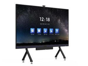
What Is an All-in-One LED Display? Uses & Key Checks
An all-in-one LED display is a direct-view LED screen that combines the display panels, power supply and display...
Read Case Study
HDR400 vs HDR10: HDR400 Is Entry-Level — What Differs
Buyers often mix up HDR400 and HDR10. HDR400 is an entry DisplayHDR brightness tier (~400 nits). HDR10 is...
Read Case Study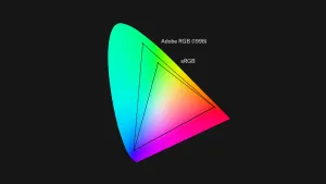
QLED vs UHD: Not Rivals — One Is a Panel, One Is a Resolution
QLED and UHD are not rivals. QLED describes how a panel makes colour (quantum-dot LCD). UHD describes pixel...
Read Case Study
Download Your
Project Specification PDF
White-labelled engineering report with your branding. Includes all calculated specifications and electrical notes.
Your data is used only for this project enquiry. No newsletters.