 All-in-One COB LED TV
  Flexible LED Displays
  Transparent LED Displays
  Led Poster
  Circular LED Displays
  Creative & Custom LED Displays
 Universities are accelerating the construction of intelligent campuses. They hope that meet the growing needs of academic conferences, information dissemination, and collaborative work. However, the LED display screen information system integrates HD display, distributed control, and audio reinforcement to create an interactive information exchange platform. Today, we will guide you design scheme of the university’s LED display information syatem.
LED Display Subsystem
System Functions
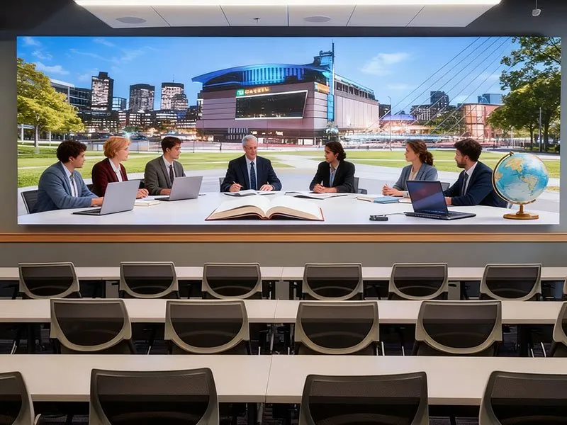
We plan to install an LED display system in the project demonstration area. It consists of a banner screen and a main display area. The complete system includes supporting equipment such as LED display panels, video controllers, intelligent power distribution cabinets, and steel structure brackets.
By dividing display windows, the large LED video wall centrally presents video resources across multiple display areas. It flexibly displays video conference images and multimedia information according to centralized control requirements.
System Deployment
LED Display Panels
After on-site surveys and preliminary design, the installation wall spans approximately 14.6 meters, the room depth is about 11.9 meters, and the ceiling height reaches 3.5 meters.

To meet usage needs, we select P1.5 small-pitch LED display. It separates the banner screen from the main display area. The main display measures 10.8 meters wide and 2.025 meters high, with an overall aspect ratio of 48:9 (equivalent to three standard 16:9 screens).

For optimal viewing from all seats, the screen is installed 0.8 meters above the ground. It has a resolution of 4320×1620.
Note that specific dimensions can be fine-tuned based on suppliers’ actual design proposals.
4K COB LED Video Wall

COB Beat
Achieves a color contrast ratio of up to 10,000:1, ensuring vibrant, clear visuals. Capture the little details even in low light. Adopting black coating technology,nonreflective surface and supreme black uniformity help to display true-to-life images
Video Controllers
The LED display’s video controllers support DP1.2 and HDMI2.0 signal inputs. Therefore, it also supports seamless switching between signal sources. They can handle up to 4K video signals at 4096×2160@60Hz, fully meeting the configuration requirements for extra-long, ultra-high, and large-scale screens.
With 20 network port outputs, the controllers can operate in single-machine mode or dual-machine redundant backup. You can get stable screen operation, high-quality image display, and flexible screen control.
We configure three video controllers for the large screen. Video sources connect via HDMI high-definition cables, and 36 Cat6 network cables link the controllers to the LED panels.
All equipment is centrally installed in a cabinet located in the equipment room. Core functions include signal switching, image pushing, splicing, pre-monitoring, and previewing.
Operators can use the visual control terminal on the control computer to dispatch any signal from the distributed command system and display it on the large screen in various layouts. It also supports window opening, splicing, roaming, overlay, and scaling.
Intelligent Power Distribution Cabinets
The hall’s LED display system adopts a 30KW intelligent power distribution cabinet with automatic control capabilities. It realizes step-by-step power-on for the display, monitors power operation status and fault information, and facilitates quick fault detection and handling.
The cabinet uses power distribution modules to control delayed start-up and shutdown, reducing grid impact during screen power cycles. Additionally, the cabinet door is equipped with manual switches for each branch and indicator lights showing power on/off status.
Steel Structure Brackets
We use high quality standard square steel to manufacture brackets for mounting the LED display panels. These brackets have structural stability and load-bearing capacity, adapting to the screen’s size and installation environment.
System Topology
Video signals connect to the video splicing controllers. Operators switch and output videos to the main LED screen based on business needs. The system requires three 4K video controllers and 38 Cat6a network cables between the cabinet and the screen ,including 2 spares.

Note that the topology diagram only illustrates functional requirements; LED display suppliers can propose optimized solutions while meeting core needs.
Distributed Transmission and Control Subsystem
System Functions
The distributed transmission and control subsystem comprises front-end and back-end components. The front end includes 4K distributed input nodes and 4K distributed output nodes. It is responsible for audio-video and control signal transmission, as well as screen splicing.
The back end consists of a visual operation and maintenance management server, a central controller, and supporting software. It can archive visualized control of equipment and images, and audio processing.
System Deployment
Large Screen Splicing Subsystem
The three video controllers of the LED display connect to corresponding 4K distributed output nodes via HDMI high-definition cables.
These nodes are centrally installed in server cabinets and linked to the subsystem network through Cat6 cables. The central service platform collaborates with the three 4K distributed output nodes to complete screen splicing.
So, it can support signal window operations such as opening, splicing, roaming, overlay, and scaling.
Operators can dispatch any signal from the distributed command system and manage multiple display groups through simple touch gestures on the control computer. By intuitive operation design, it allows for flexible switching, splicing, display, roaming, and overlay without complex configurations.
Visual Command and Control Subsystem
Adopting visualized and networked management, the subsystem centrally controls all venues. It can offer real-time signal preview for over 20 channels. Moreover, It supports multiple display terminal echo windows, ensuring synchronization between echo content and the large screen.
The user-friendly interface is graphically based and touch-operated. With multi-touch functionality, operators can zoom, move, or close signal windows, achieving WYSIWYG (What You See Is What You Get) control.
The system implements multi-level permission management:
- Different permissions correspond to distinct management interfaces and content.
- Administrators hold the highest authority to configure system functions.
- Authorized users can independently control, dispatch, and manage resources within their scope.
- End-users operate the system via the visual central control interface without worrying about backend equipment or configurations.
For scenario-specific needs, the system supports plan management. Operators can configure signal combinations, audio modes, and other parameters for different occasions. It can also archive one-click invocation and switching of multiple plans. For example, signal switching, screen presentation, and audio routing can be pre-saved as plans based on different operation scripts, which are dispatched in sequence during use.
KVM Seat Management Subsystem
The distributed seat collaboration system enhances work efficiency by allowing signal push between seats, from seats to the large screen, and to management seats.
Push modes can be set to active or passive reception. With flexible and rigorous permission management, administrators can assign or revoke permissions for each user ID, ensuring secure and orderly resource access.
Central Control Subsystem
The central control subsystem integrates 4K distributed output nodes, 4K distributed input nodes, a central control host, a central service platform, and supporting software.
Controlled devices in the room, such as, LED screens, cameras, lights, curtains, air conditioners, computers etc. Thye connect directly to nearby distributed nodes via control cables. Operators use the visual control terminal on the control computer to centrally manage all these devices, simplifying operation and improving work efficiency.
Note that the above deployment descriptions only outline functional requirements.
LED display suppliers can propose more advanced distributed system solutions as long as core functions are met.
System Topology
The topology diagram illustrates basic functional logic. Suppliers are encouraged to optimize the structure based on technical capabilities and project needs.
Audio Sound Reinforcement Subsystem

System Functions
High-quality, clear sound should be evenly distributed across the entire meeting room seating area. To achieve this, designers adjust speaker positions and angles to ensure uniform direct sound coverage.
By calculating the reverberant sound field in the listening area, the system overcomes background noise while maintaining speech intelligibility. It predicts sound arrival at specific audience positions to eliminate echoes, ensuring every participant can hear clearly.
System Deployment
Audio Processing Subsystem
The audio sound reinforcement subsystem meets requirements for video command and local sound reinforcement. It has high fidelity, real-time performance, and stability. In addition, It realizes local voice pickup and playback with clear audio, no interference, uniform sound field, and sufficient sound pressure level without feedback.
Leveraging advanced audio coding and decoding technology, network technology, and computer technology, the subsystem supports cross-functional area audio signal sharing, interconnection, and centralized management.
Composed of a digital audio matrix processor, digital mixer, power amplifier, and feedback suppressor, it offers rich functions with a simple configuration and easy operation. The system easily connects to other systems’ audio signals, boasts strong anti-interference capabilities, simplified wiring, and high reliability.
Sound Reinforcement Subsystem
The deduction room’s sound reinforcement system includes 2 main speakers and 2 ceiling speakers, while the analysis area is equipped with 2 ceiling speakers.
The design prioritizes speech intelligibility and uniformity, followed by sufficient dynamic range and low-frequency extension for video playback. Considering potential long reverberation time due to suboptimal architectural acoustics, the system adopts distributed coverage.
Active adjustable-direction main speaker arrays and subwoofers are installed on both sides of the LED screen to enhance speech intelligibility, while ceiling speakers serve as backups to improve system reliability.
Conference Subsystem
The conference subsystem consists of a digital conference system and a video conference system. We select a well-known the digital conference system, which uses a daisy-chain connection. The speaking units are portable and easy to install. It has an elegant design and minimal wiring that does not affect the overall decoration.
Based on the meeting room layout and needs, the configuration includes:
- 1 digital conference host (core control and management unit);
- 1 chairman unit;
- 17 delegate units.
System Topology
The topology diagram outlines the audio system’s structure. Suppliers can propose optimized solutions to meet functional requirements.
Conclusion
This colleage LED display information construction design scheme integrates three core subsystems:
- LED display
- Distributed transmission and control
- Audio sound reinforcemen.
It can create a comprehensive, intelligent information platform.
In practice, the system will enhance the university’s information dissemination efficiency, improve meeting quality, and lay a solid foundation for the construction of a smart campus. As technology advances, the system can be further upgraded to integrate emerging technologies such as AI and IoT, realizing more intelligent and personalized application scenarios.