 All-in-One COB LED TV
  Flexible LED Displays
  Transparent LED Displays
  Led Poster
  Circular LED Displays
  Creative & Custom LED Displays
 When working with NovaStar LED control systems, users occasionally encounter issues during setup or daily operation.
Doitvision summarizes 23 of the most frequently reported problems and offers practical solutions. We hope this post will help you identify and resolve common pitfalls.
1. Screen Displays Incorrectly During Smart Settings

- Make sure the sending card resolution matches the graphics card output resolution. If they differ, adjust them to be the same.
- If the resolutions already match, check whether you have entered the correct parameters in the Smart Settings Wizard or loaded the correct receiving card configuration file.
2. [No Hardware] Shown in LCT Mars Software
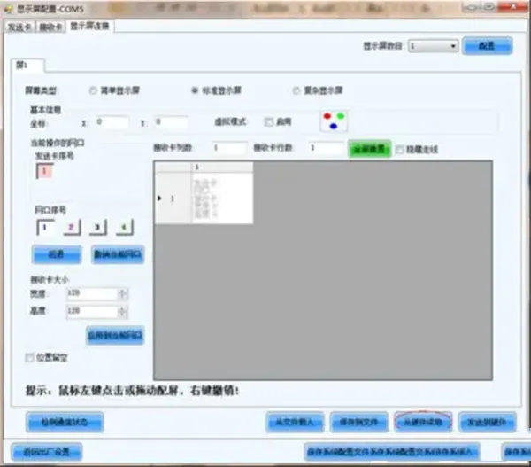
- Confirm that all hardware devices are powered on.
- If you’re using a synchronous system, verify the USB serial cable is connected properly.
- Ensure the USB serial driver is correctly installed.
3. [No Screen Information] in LCT
- If the screen was previously configured, go to Display Connection > Read from Hardware, then send and store the screen connection (SCRFG) file.
- If configuring for the first time, set up the screen connection according to the actual cabinet layout on the Display Connection page.
4. Only Part of Each Cabinet Displays Normally During Smart Settings
- Confirm the receiving card’s load module settings match the actual cabinet structure.
- Check whether the receiving card’s width and height in pixels match the cabinet’s actual pixel dimensions.
5. LCT Displays [Error Notice] During Operation

- If the PC is connected to the internet, click Send Error Report and contact NovaStar technical support.
- If offline, click View Error Data, copy the data into a TXT file, and then contact technical support.
6. Receiving Card Indicator Light Status (Synchronous System)
(Content not provided. Consider referencing the official documentation for LED light behavior.)
| Indicator Light | Status | Represented Meaning |
|---|---|---|
| Red Light | On | Receiver card power supply is normal |
| Off | Receiver card has no power supply | |
| Green Light | On | Receiver card authorization has expired |
| 1Hz flashing (1 flash per second) | Normal operation, image data comes from main channel | |
| 2Hz flashing (0.5 seconds flash once) | Normal operation, image data comes from bypass channel (redundant mode) | |
| 7Hz flashing (0.15 seconds flash once, fast flash) | Receiver card is in boot mode, indicating that the program has not been successfully loaded | |
| 0.2Hz flashing (5 seconds flash once, slow flash) | Network cable is disconnected or has no network connection | |
| Intermittent flashing, fast flash 3 times, then black for 0.5 seconds, fast flash 3 times again, then black for 0.5 seconds, repeating this cycle | Connected to the sender card normally, but the sender card DVI has no signal input |
7. Sending Card Indicator Light Status (Synchronous System)
(Content not provided. Refer to NovaStar’s official LED behavior chart.)
| Indicator Light | Status | Meaning |
|---|---|---|
| Green Light | Normal Blinking: 2.98Hz; 0.3S blink once | FPGA is working normally |
| Fast Blinking: 23.8Hz; 42mS blink once | Boot screen | |
| Slow Blinking: 0.37Hz; 2.7S blink once | No signal screen, no DVI signal | |
| Always Off | FPGA not working, or FPGA in expiration | |
| Red Light | Always On | Working normally, can be understood as power-on indicator |
| Fast Blinking: 20Hz; 50mS blink once | Authorization expired, and green light is always off |
8. LCT Mars Cannot Detect the Light Sensor
- Confirm the USB serial cable from the sending card is properly connected.
- Check that the light sensor is correctly connected to the multifunction card or sending box.
- Make sure the sensor has been added via serial port or network mode in the multifunction card interface.
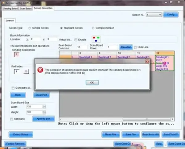
9. [Crossing Two DVI Signals] Prompt During Screen Connection
- This means the screen resolution exceeds the video source’s resolution. Try using a higher-resolution signal source or enable extended desktop mode.
- Double-check the total pixel count in the cabinet layout and ensure it’s correctly set in the topology diagram.
10. Multi-Sending Card Backup Has No Effect
- Confirm that the screen connection matches the primary/backup controller configuration.
11. USB Serial Port Connected but Device Not Found

- Ensure that the USB driver is properly installed.
- Try a different USB port on the control PC.
- Enable the corresponding serial port on your computer.
12. Screen Freezes or Displays a Default Image When Signal is Lost
- Go to Tools > Pre-stored Image Settings and configure what the screen should display when disconnected.
13. Computer Doesn’t Auto-Duplicate DVI Signal After Connecting to Sending Box

- Check whether the graphics card driver is installed.
- On Windows XP, open the NVIDIA or CCC control panel after driver installation to manually configure display duplication.
- On Windows 7 and above, DVI duplication should happen automatically upon device connection.
14. Screen Image Shifts with Mouse Movement Even After Correct Smart Settings

- Verify that the sending card resolution matches or closely matches the graphics card resolution on the Sending Card page.
15. No Effect After FPGA Update on Sending and Receiving Cards
- Double-check the model numbers of both sending and receiving cards.
- Ensure you’ve selected the correct firmware package in the DATA list before upgrading.
16. No Module Display Changes During Smart Settings
- Make sure all module parameters are correctly set:
- Data type: Serial or parallel drive.
- Chip type: Match with actual LED module.
- OE polarity: High or low active, usually default.
- Module type: Regular or irregular.
- Pixel count: Set according to module size.
- Data groups: If unknown, select “Unknown.”
- Row decoding: Choose from 74HC138, static, or direct.
- Scan mode: Match actual scan configuration or set to “Unknown.”
- Receiving card load module: Typically 1 row × 1 column.
- Cascade direction: Set based on actual wiring.
17. Receiving Card File Import/Export/Send Fails
- Ensure USB or network cables are securely connected.
- Confirm the receiving card file matches the actual cabinet configuration.
- For irregular cabinets, upgrade to a newer LCT version that supports exporting for special shapes.
- Try switching to another sending card.
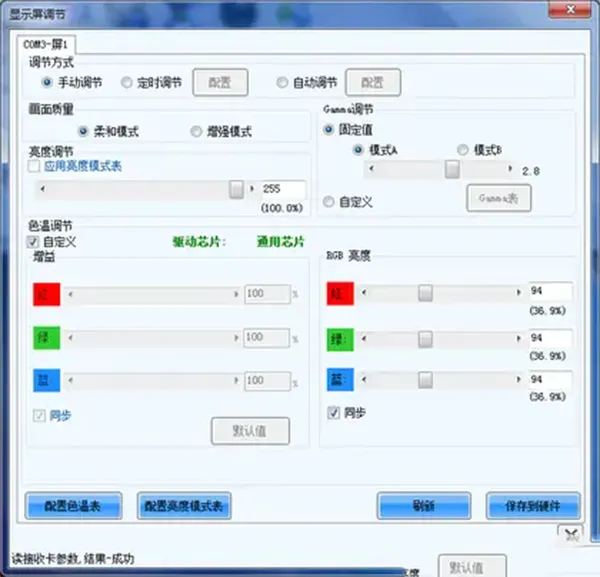
18. Screen Appears Dim at Full Brightness in RGB Test

- Navigate to Brightness > Screen Adjustment and check if gain percentage is properly configured.
19. Display Works but is Unresponsive to Control
- Go to Screen Control and make sure the [Lock] function is disabled.
20. Monitoring System Fails to Send Email Notifications
- Check the email address for typos.
- Verify the control PC is connected to the internet.
- Ensure system time is correctly synced.
21. Unable to Debug Without a Sending Card
- Receiving cards must be MRV300 or higher.
- LCT software must be v4.4.0 or above, with USB drivers and WinPcap 4.1.3 or higher installed.
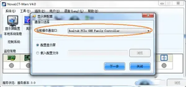
- Confirm the communication port is set to the correct gigabit Ethernet interface.
22. Some Cabinets Appear Brighter Than Others
- Receiving card configurations may differ; try reading a receiving card file and sending it to all cards.
- Receiving card FPGA versions may be inconsistent; upgrade them to the same version.
23. Flickering or Noise in Low-Gray Mode
- Ensure the hardware system isn’t exposed to strong electromagnetic interference.
- Check that all receiving cards use the same FPGA version and upgrade if necessary.
Conclusion:
By following this guide, you can swiftly resolve many of the most common issues when Debugging NovaStar control systems. If you need help creating an optimized configuration file or remote setup? Let us know — we’re here to help.