 All-in-One COB LED TV
  Flexible LED Displays
  Transparent LED Displays
  Led Poster
  Circular LED Displays
  Creative & Custom LED Displays
 Novastar’s redundancy solution uses dual system hot backup, controller optical fiber and other key components. When any one fails, it can restore normal display without manual intervention, and send out an alarm signal through dedicated software.
Redundancy description:
- If any controller fails, it can be switched to hot backup, and the display screen will not be black;
- If any optical fiber fails, it can be switched to hot backup, and the display screen will not be black;
- If any network cable fails, it can be switched to hot backup, and the display screen will not be black;
System backup architecture diagram
Nova control system, hot backup function is simple and convenient to operate. It has strong stability and can play an important role in any situation. Its architecture is also very simple, with two modes:
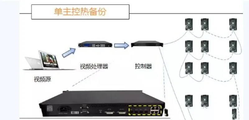
Single controller backup

Backup between two (multiple) controllers.
As shown in the following figure: Single master control hot backup architecture diagram Dual (multiple) master control hot backup architecture diagram
Solution 1 Single controller backup
Hardware connection as shown in Figure:

Network cables 1 and 2 are used as the main signal to light up the screen.
Software interface settings:

Set the “sending card”, “receiving card”, and “display configuration” in the software and solidify them.
For example, in the figure above, send the display configuration diagram to the sending card according to the direction of network cable 1 and network cable 2.
Solidify the parameters after the screen is normal.
Set the backup information:

In the “sending card” interface, as shown in the figure above,
- Figure Refresh: refresh the current redundancy status of the sending card to check whether the device has backup information;
- Edit: change the redundancy settings;
- Delete: Delete the current redundancy settings; set the backup information in the “red box” on the software.
Click “Add” to add backup information. For example, if network port 3 backs up network port 1, set it as shown in the figure.

Then click “Add” to add backup information.
Network port 4 backs up network port 2 as shown in the figure.

After adding information, click “Close” to close this dialog box.
You can see the backup information as shown in the figure.

Click “Send” to send the backup information to the sending card. And click “Solidify” to save the backup information.
Connect the backup network cable 3 to network port 3, and the backup network cable 4 to network port 4.
After the backup is completed, the hardware connection of the system is as shown in Figure
Network cable 3 is connected to the output port of the end receiving card carried by network cable 1, and the other end is connected to the network port 3 of the sending card;
Network cable 4 is connected to the output port of the end receiving card carried by network cable 2, and the other end is connected to the network port 4 of the sending card.
Note:
- It is recommended to connect the backup network cable 2 after all parameters (sending card, receiving card, display configuration, brightness, backup information, etc.) are set.
- The corresponding relationship of the backup network port can be specified arbitrarily, and network port 4 can also be used to backup network port 1, and network port 2 can be used to backup network port 3, but the network cable must be connected correctly.
- After the backup setting is completed, the main network cable can be plugged in and out to confirm whether the backup is successful.
Solution 2 Backup
Hardware connection between dual (multi) controllers is shown in Figure :

Network cables 1, 2, 3, and 4 are used as the main signal to light up the screen.
Software interface settings:
Set the “sending card”, “receiving card”, and “display configuration” in the software and solidify them.
Send the display configuration diagram to the sending card according to the direction of network cable 1, network cable 2, network cable 3, and network cable 4.
After the screen is normal, solidify the parameters.
Set the backup information: In the “Sending Card” interface, as shown in Figure
- Refresh: Refresh the current redundancy status of the sending card to check whether the device has backup information;
- Edit: Change the redundancy settings;
- Delete: Delete the current redundancy settings;
Set the backup information in the “red box” on the software.
Click “Add” to add backup information.
For example, if the network port 1 of sending card 2 backs up the network port 1 of sending card 1, then set it as shown in Figure

then click “Add” to add backup information.
The network port 2 of sending card 2 backs up the network port 2 of sending card 1 as shown in Figure

Set the remaining network ports in this way. After adding information, click “Close” to close this dialog box.
Click “Send” to send the backup information to the sending card. And click “Solidify” to save the backup information.
Connect the backup network cables 5, 6, 7, and 8 to the network ports of the backup sending card. l The backup is completed. The hardware connection of the system is as shown in Figure:

Note:
- It is recommended to connect the backup network cable 2 after all parameters (sending card, receiving card, display configuration, brightness, backup information, etc.) are set.
- The corresponding relationship of the backup network port can be specified arbitrarily. You can also use network port 4 to back up network port 1, and network port 2 to back up network port 3, but the network cable must be connected correctly.
- After the backup settings are completed, you can plug and unplug the main network cable to confirm whether the backup is successful.