All-in-One COB LED TV
 Flexible LED Displays
 Transparent LED Displays
 Led Poster
 Circular LED Displays
 Creative & Custom LED Displays
Flexible LED modules bend — but not infinitely. Every module has a hard mechanical limit defined by its minimum cylinder diameter, not by pixel pitch. Here is exactly how it works, what the numbers are (764mm for 240×120, 815mm for 320×160), why the internal structure enables bending at all, and the three ways installers accidentally destroy flexible modules.

- DOIT VISION flexible LED modules have a minimum cylinder diameter of 764mm (240×120mm modules) or 815mm (320×160mm modules) — the tightest cylindrical column they can safely wrap
- Bending angle reaches 145° to 165° — tight enough for “S” curves, waves, and near-complete cylinder wraps
- The modules bend because they use a polyimide (PI) flexible PCB with serpentine copper traces inside a silicone rubber chassis — completely different from rigid FR-4 fiberglass boards
- Over-bending beyond the limit causes copper trace micro-cracks — dead pixels appear days or weeks later, and the damage is not covered by warranty
Minimum Cylinder Diameter — 764mm & 815mm, Not by Pixel Pitch
The bending limit of a flexible LED module is determined by its physical module size, not by its pixel pitch. A P1.25 module and a P4 module — in the same 240×120mm form factor — share the same minimum cylinder diameter of 764mm because the PCB substrate and silicone chassis dimensions are what constrain the bend, not the pixel spacing.
| Module Size | Available Pitches | Min Cylinder Diameter | Radius | Smallest Wrap Target | Bend Angle |
|---|---|---|---|---|---|
| 240×120mm | P0.9375(COB)–P4 | 764mm | 382mm | ≥764mm diameter column | 145–165° |
| 320×160mm | P1.25–P4 | 815mm | 407.5mm | ≥815mm diameter column | 145–165° |
A 600mm-diameter architectural column in a shopping mall lobby? Neither module size can wrap it. The column diameter must be at least 764mm for the 240×120 module or 815mm for the 320×160 module. This is the first — and most important — feasibility check for any flexible LED project.
Note that “minimum bend radius” as a general engineering concept ranges from 30mm to 100mm depending on the specific module construction. But the practical constraint for an entire cylindrical display is the minimum cylinder diameter — 764mm or 815mm — because you must be able to mount the modules securely around a structure without the PCB cracking at the mounting points.

Bending Angle: 145°–165° — What That Means in Practice
DOIT VISION flexible LED modules can withstand bending angles of 145° to 165°. This is not the angle of the curve itself — it describes how far the module’s shape can deviate from flat. At 165°, the module is nearly folded back on itself, forming an extremely tight “U” shape.
- Smooth “S” curves on stage backdrops
- Gentle concave lobby walls
- Wide column wraps
- Less stress on solder joints
- Tight cylinder wraps near minimum diameter
- Sharp wave-shaped displays
- Maximum stress — must verify mounting points
- Requires precise frame radius control
- Stay at 150° or below for long-term reliability
- Push to 165° only for specific creative effects
- Check manufacturer spec for your exact module model
In practice, most installations do not need the full 165° range. A typical corporate lobby curved wall might use a 20–40° gentle arc. A column wrap at 764mm diameter achieves roughly 160° per module segment. The 145–165° range gives you headroom to achieve the creative shapes your architect draws — just make sure the structural frame is built to the same curve specification as the modules.
Why Flexible LED Can Bend — The 5-Layer Internal Structure
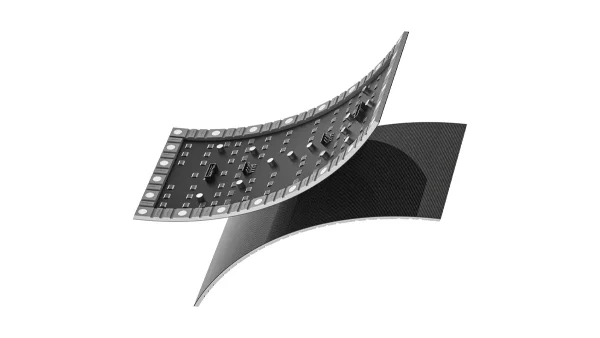
A flexible LED module is not a normal LED panel that someone somehow made thinner. It is a fundamentally different construction. Every layer — from the outer mask down to the magnetic base — is designed to bend without breaking.
High-grade silicone or specialized rubber. Protects LEDs from impact and moisture. Matte finish reduces glare. Because it is soft, it allows the entire module to bend freely without cracking — unlike the hard plastic mask on a rigid LED panel.
A protective adhesive layer covering the LED surface. DOIT VISION developed a flexible GOB formulation — unlike traditional rigid GOB, this coating bends with the module while providing waterproofing, dust protection, and impact resistance. Reduces pixel damage by 99% during installation.
This is the “brain” and the component that makes bending possible. Made of Polyimide (PI) film — not FR-4 fiberglass. Heat-resistant and highly pliable. The copper traces are laid in serpentine (zigzag) patterns rather than straight lines, allowing them to stretch slightly without snapping. The FPC costs roughly twice as much as a standard rigid PCB.
Located on the back of the FPC. These tiny chips control brightness and colour for each pixel. Encapsulated in protective resin to keep them secure during bending. Because the back of a flexible module has limited space, these tend to be higher-performance ICs than those found on rigid modules — supporting up to 7680Hz refresh and 18-bit colour on certain models.
A flexible, magnetic base made of high-strength silicone rubber. Each module contains up to 28 neodymium magnets on the underside, allowing it to “snap” onto a curved steel frame without tools. The silicone chassis absorbs and distributes bending stress across the entire module back, preventing stress concentration at individual mounting points. The magnets are height-adjustable — they can be rotated to compensate for uneven installation surfaces and maintain a flush, continuous display face.
The module is 5–10mm thick total. A standard rigid LED module is 15–20mm. This thinness is not just for aesthetics — the thinner the material, the less mechanical stress is applied to the surface when bent. The stress is distributed throughout the material rather than concentrating at a crack point.
Flexible vs Rigid LED — The Material Difference at Every Layer
When an installer tries to bend a rigid LED module, it snaps — instantly and permanently. The difference is not incremental. It is a completely different set of materials at every layer of the module stack.
| Component | Rigid LED Display | Flexible LED Display |
|---|---|---|
| Base Material (PCB) | Fiberglass (FR-4) — rigid, brittle | Flexible Polyimide (PI) Film — bends freely |
| Housing / Chassis | Plastic or Metal Cabinet — rigid enclosure | Flexible Silicone / Rubber Substrate — soft, conforms to curves |
| Copper Traces | Thick, straight copper traces — snap under stress | Flexible Rolled Annealed Copper in serpentine pattern — stretches slightly |
| Module Thickness | 15–20mm | Thinner 5–10mm |
| Reaction to Force | Snaps / Cracks — permanent failure | Flexible Absorbs / Conforms — returns to shape |
There is another subtle difference: the LED chips themselves. Individual LED chips on the diode board are rigid — they are tiny ceramic packages that cannot bend. But because each chip is so small (roughly 1mm × 1mm for a 1010 package), they act like “links in a chain.” The spaces between the chips are where the bending happens. The flexible solder and conductive adhesives used in assembly prevent the chips from detaching when the FPC underneath bends.
Flexible and rigid LED modules at the same pixel pitch use the same SMD LED packages, deliver the same colour reproduction, and achieve the same 3840Hz refresh rate. The flexible module achieves better continuous splicing on curves — because the module itself conforms to the curve, there are no “grid lines” or facet lines between modules that you get when trying to tile rigid panels around a curve with angled brackets.
Three Ways Installers Accidentally Destroy Flexible LED Modules
Trying to wrap a 240×120mm module around a 500mm-diameter column. The copper traces stretch too far. Micro-cracks form. Pixels go dark — not immediately, but over the next weeks as the cracks propagate. The damage is progressive and irreversible. Always check: is the column diameter ≥ 764mm?
Flexible modules are designed to be bent into a shape once and stay there. Repeatedly bending them back and forth — like folding a piece of paper — causes metal fatigue in the copper traces. Deployable/reconfigurable setups should use rigid modules on adjustable brackets instead.
A structural frame built to a 900mm radius when the modules are rated for 764mm minimum. The modules physically fit but are under constant tension at every mounting point. This chronic stress fatigues the PCB over months and eventually causes delamination between the FPC and the silicone chassis. Always match the frame radius to the module specification.
A failed flexible module due to over-bending is not always obvious. If a module looks fine but shows random flickering pixels or horizontal dead lines after a few weeks of operation — check the bend condition. The most likely cause is copper trace fatigue from exceeding the bend limit.
Column Wrap Feasibility — How to Check Before You Order
Column wraps are the most common flexible LED application. The feasibility check is three simple measurements that determine whether a project is possible before you spend a dollar on modules.
-
Step 1 — Measure the column diameterUse a measuring tape around the column circumference. Diameter = circumference ÷ 3.1416. If the diameter is less than 764mm, you cannot wrap it with standard DOIT VISION flexible modules — regardless of pixel pitch.
-
Step 2 — Choose your module sizeIf column diameter is ≥ 764mm but < 815mm, you must use 240×120mm modules. If it is ≥ 815mm, either 240×120 or 320×160 will work — choose based on your preferred pixel pitch range.
-
Step 3 — Calculate the module countColumn circumference ÷ module width (or height, depending on orientation) tells you how many modules fit around the column. Add one extra module to the count for tolerance. Order 3–5% spare modules for on-site replacement.
WhatsApp a photo of the column, the column diameter measurement, and your preferred pixel pitch to our engineering team. We confirm technical feasibility within 24 hours and send back a module layout drawing showing exactly how many modules fit around the column, where the seams will be, and how the structural frame should be fabricated. If the column is too small for standard modules, we discuss custom module options.
Bend Limits — Questions Integrators Actually Ask
What is the minimum bend radius of a flexible LED display?
DOIT VISION flexible LED modules are specified by minimum cylinder diameter — 764mm for 240×120mm modules and 815mm for 320×160mm modules. This means the smallest cylindrical column you can wrap is 764mm in diameter for the smaller module size. Bending angle reaches 145° to 165°. Exceeding these limits causes copper trace micro-cracks and permanent LED failure not covered by warranty.
Why can flexible LED modules bend?
Flexible LED modules use a fundamentally different construction from rigid LED panels: (1) a flexible PCB made of polyimide (PI) film instead of rigid FR-4 fiberglass, (2) copper traces laid in serpentine (zigzag) patterns that can stretch slightly, (3) a soft silicone rubber chassis instead of a hard plastic cabinet, and (4) ultra-thin 5–10mm design that distributes bending stress across the entire module rather than concentrating it at one point. Individual LED chips are small enough that the bending happens in the spaces between them.
What happens if I bend a flexible LED module too far?
Over-bending stretches the copper traces beyond their elastic limit, creating micro-cracks. Symptoms include dead pixels (not immediate — often appearing days to weeks later), horizontal lines of dead LEDs, random flickering, and PCB delamination from the silicone chassis. The damage is progressive and irreversible. Also: repeatedly bending modules back and forth causes metal fatigue in the circuitry. Flexible modules are designed to be bent into a shape once and stay there.
What is the minimum column size I can wrap with flexible LED?
764mm diameter for the 240×120mm module size. 815mm diameter for the 320×160mm module size. If your architectural column is smaller than 764mm in diameter, standard DOIT VISION flexible modules cannot wrap it. Contact engineering to discuss custom module options.
What is the difference between flexible LED and rigid LED in terms of materials?
Rigid LED uses FR-4 fiberglass PCB with straight copper traces inside a plastic or metal cabinet, 15–20mm thick — bends snap and crack permanently. Flexible LED uses polyimide film PCB with serpentine copper traces inside a silicone rubber base, 5–10mm thick — absorbs and conforms to curves. Flexible PCB costs roughly twice as much as rigid PCB. Visual performance (colour, refresh rate, resolution) is identical at the same pixel pitch.
How do I check if my column wrap project is feasible?
Three steps: (1) Measure the column diameter — circumference ÷ 3.1416. If it is less than 764mm, standard modules cannot wrap it. (2) Choose module size — 240×120mm for columns 764–815mm, either size for columns ≥815mm. (3) Calculate module count — column circumference ÷ module width tells you how many modules fit around. Send a photo of the column with the diameter measurement to DOIT VISION engineering for a free feasibility check and module layout drawing within 24 hours.
Want the numbers without the maths? Use the column diameter feasibility chart — 14 common column sizes with module counts already calculated. Full mechanical specifications for all module sizes are on the Flexible LED Series product page.
19 years in LED display engineering. Writes the bend tolerance specifications DOIT VISION quotes to AV integrators in 55+ countries. Every number in this article comes from our own module test data, not a datasheet reprint.
Photo of the column + diameter measurement + preferred pitch. Our engineer confirms technical feasibility and sends back a module layout drawing — before you commit to a purchase order. No charge, no obligation.